hot head on a cool stage.
3D Metal Jet Printing is about printing products…
Read MoreIn this article, we present the model-based design steps for a high-performance vibration isolation system to support a metrology frame. During the design phase, several improvements were shown to increase the vibration isolation performance. The design requirements for the individual spring and damper components have been derived from the relatively simple model. To conclude, the realisation of these components is briefly discussed.
BAS LEMMEN, RANDY SMEENK AND JANNO LUNENBURG
In the production of complex systems, consisting of many modules, any production deficiencies are increasingly difficult to track down as the production process progresses. Therefore, it is essential that the individual modules are ‘qualified’ before they are integrated into the system. The qualification process includes tests, e.g. to check electrical connectivity, proper functioning of sensors and actuators, and hydraulic and pneumatic circuits for leakage or blockages.
To discover any mechanical deficiencies such as loose bolts or glue errors, the transfer function of the device under test (DUT) can be measured to determine non-rigid-body dynamics. Specific (anti-) resonant frequencies can be used to identify any production defect as well as give an indication for end-product performance.
Ideally, the sensors to measure this transfer function are mounted on a fixed, separate metrology frame (MF) such that the sensors themselves do not move along with the device, as this would disturb the measurements. This static MF contains sensors that measure the displacements of the DUT with high accuracy.
The traditional solution is to separate the MF from the force frame and fixate it to the machine floor. What can we do, however, if this is not possible due to practical limitations? In this article, we discuss how a simple 1D mass-spring-damper model was used to develop a concept support frame, from which the design specifications of the eventual system were derived.
Furthermore, we present the realisation of the solution and compare it to the simplified initial model to underline the effectiveness of the model-based approach for this system. Figure 1 shows the simple ‘model’ representation of the measurement system. The red block designates the base frame (BF) on which the DUT is placed for qualification. The DUT itself is designated by the cyan and green blocks and corresponding springs and dampers. The DUT support is indicated with a purple block. The MF is represented in yellow.
Hence, the main question is how to connect the yellow block to the red block in such a way that the actuator forces Fact and the external vibrations do not excite the MF. In the following section, we elaborate the requirements and the corresponding challenges in more detail, followed by a description of the evolution of the concept design. Thereafter, the resulting mechanical design and corresponding analysis results are discussed.
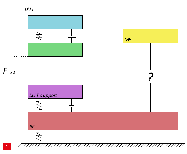
The dynamical model in the ideal world if there is no connection between the metrology frame MF and the base frame BF.
As mentioned above, we need to design a support for the MF that isolates the MF from vibrations and disturbances of the DUT (actuation) and other sources, e.g. floor noise, operator handling or acoustic disturbances. Frequencies below 100 Hz are of no significance for this application, because the expected eigenmodes of the DUT are all above this frequency, even in the case of defects.
For the relevant measurement range of 100 to 5,000 Hz, a disturbance attenuation of 8 to 10 orders of magnitude needs to be achieved to reach sufficient measurement performance. The general design goals are:
• Attenuation of disturbances from actuation forces and floor noise by at least 8 orders of magnitude in the frequency range of 100 to 5,000 Hz.
• Damping of any (residual) motion for the MF to ensure its proper standstill during measurement.
Note that the first design goal suggests an MF that is highly decoupled from the BF, while the second goal requires a damping force to be coupled to the MF. In the ideal situation, a standstill MF is designed without any mechanical interface between either DUT or floor and the MF, so that no disturbances can travel from the DUT to the MF. This ‘skyhook’ approach would be the optimal solution, but is not possible for obvious reasons.
As a start, a simple design is realised via a flexible support between the MF and the BF, i.e. the question mark in Figure 1 has become a spring. The eigenfrequency can be tuned using the spring stiffness. With this connection, any motion from the BF will excite the MF. The transfer function from the actuator force Fact to the vertical displacement of the MF is shown in Figure 2. The low frequency resonance peaks represent the eigenfrequencies of the BF and the MF. The peak in the frequency area of interest represents the eigenfrequency of the DUT. The vibration isolation requirement is based on the slope of the mass line of the DUT. The model shows that the vibration isolation requirement is already satisfied.
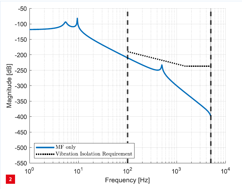
Magnitude plot of the transfer function from the actuator force Fact to the vertical displacement of the metrology frame MF when it is connected via a fixed support to the base frame.
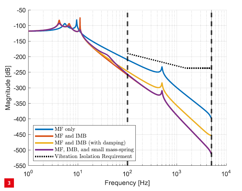 Magnitude plot of the transfer functions for the various concepts; see the text for further explanation.
This model, however, is a simplification of the real situation where more eigenfrequencies and noise are present. For high frequencies, the vibration isolation requirement becomes flat due to the effect of noise that dominates for high frequencies in the real application. The question is how to decrease the transfer function in the frequency area of interest (between 100 and 5,000 Hz, indicated with the vertical dashed lines) in order to suppress the disturbances and ensure that the vibration isolation requirement is satisfied for the real-world application.
The mass-spring-damper model introduced above is used to analyse different concepts in order to investigate how the requirements of the previous section can be met. This approach enables quick iterations with different values of mass, spring constant and damping coefficient and can be implemented in Matlab. The resulting transfer functions for the various concepts are displayed in Figure 3.
The first step to improve the dynamical behaviour compared to a spring-damper between the BF granite stone and the MF is to add an intermediate body (IMB) between the BF and the MF, as illustrated in Figure 4.
The IMB adds a (low) eigenfrequency and a decoupling, which results in the required disturbance attenuation in the frequency area of interest; see the red line in Figure 3.
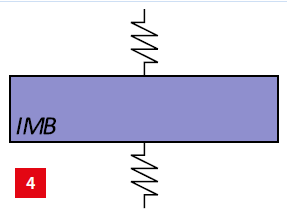
The intermediate body IMB, with corresponding fixed supports (springs), that is added between the base frame and the metrology frame.
Adding the IMB yields an additional low-frequency resonance peak due to the eigenfrequency of this body. This results in a decrease in magnitude of the transfer function and ensures that the vibration isolation requirement is satisfied. Due to the low eigenfrequency, the motion of the MF is only low-frequency. However, the rigid connection does not add damping to the system. If no or little damping is present, the MF vibrates for a long time, as can be seen in Figure 5a. This is obviously undesired.
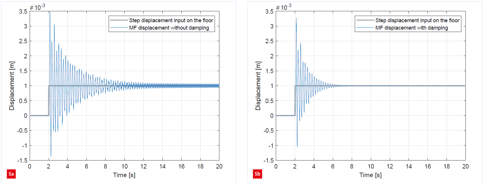
Resulting displacements of the metro frame MF due to a step displacement exerted on the floor.
(a) Without damping.
(b) With damping.
Figure 6 illustrates the IMB with an additional damper between the IMB and the BF. This adequately damps the MF vibrations, as can be seen in Figure 5b. Damping, however, comes at the cost of a deteriorated transfer function from the DUT to the MF. This effect can be clearly observed in the frequency domain; see the yellow line in Figure 3. The low-frequency resonance peaks are damped and the disturbance attenuation in the frequency area of interest deteriorates.
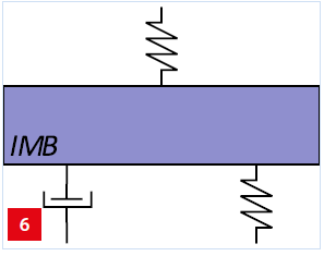
The intermediate body IMB, together with a damper and its springs, that constitutes the connection between the metro frame and the base frame.
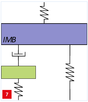
The intermediate body IMB together with another small massspring, damper and corresponding springs.
To get the best of both worlds, another small mass-spring can be added below the damper, see Figure 7. At low frequencies, the spring is stiff and damping is present in the system. For higher frequencies, the damper is stiff and is decoupled from the system such that damping is no longer present. The resulting transfer function is displayed as the purple line in Figure 3.
Low frequencies are damped due to the small mass-spring. For frequencies in the area of interest, the transfer function decreases and the vibration isolation requirement is satisfied including sufficient design margin.
Below, we will discuss the realisation of several spring and damper components as have been derived above.
The insights obtained from the last concept discussed above have been incorporated in the mechanical design of the support frame. Figure 8 shows the concept of the dynamical model together with the realisation of the springs and damper for the eventual system. It can be seen that the resulting mechanical components are simple components, i.e. the three modelled springs are all laser-cut sheet-metal parts and the damper was created as an Eddy-current-damper using an aluminium plate moving in between two checkerboard magnet yokes. Note that the checkerboard pattern allows damping in two directions. By tuning the checkerboard pitch, the damping coefficient can be tuned separately in both directions.
To analyse the design, we derived FEM models of both the qualification tool and the DUT from their respective CAD models. These were used for modal analysis and the resulting state-space models were imported into Matlab and combined into one dynamic model. This dynamical model is described by a state-space model with six degrees of freedom (6-DoF), which contains more information and details compared to the 1D model described in the previous section.
The resulting transfer function in the z-direction of the centre of the MF was compared with the 1-DoF model in Figure 9. Here, it could be seen that both models match well at low frequencies. At higher frequencies, dynamics that have not been considered in the 1-DoF model cause a deviation between both models. Note that the design margin between the requirement and the simple model has proven sufficient to ensure that the performance of the full model also is within specification. A similar analysis has been performed on the other DoFs, showing comparable results.
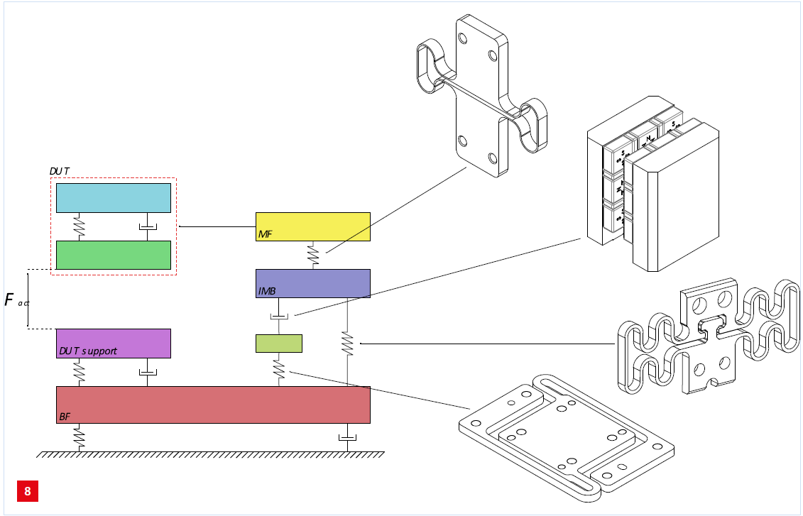
Concept model and, on the right, the mechanical realisation.
In this article, we have shown how model-based design was applied to designing a support for a metrology frame for a qualification tool. Starting from the initial ‘ideal’ model, we added intermediate bodies, springs and dampers, in order to i) support the MF, ii) absorb energy to reduce excitation of the MF, and iii) decouple the damper so that the effect of both actuation forces and floor vibrations on the MF is minimised. Each additional body-spring-damper combination adds design freedom to shape the relevant transfer functions to meet the requirements.
Finally, we have shown how FEM and modal models were used to demonstrate that the dynamic behaviour of the resulting design corresponds well to the simple model and therefore meets the vibration isolation requirements.
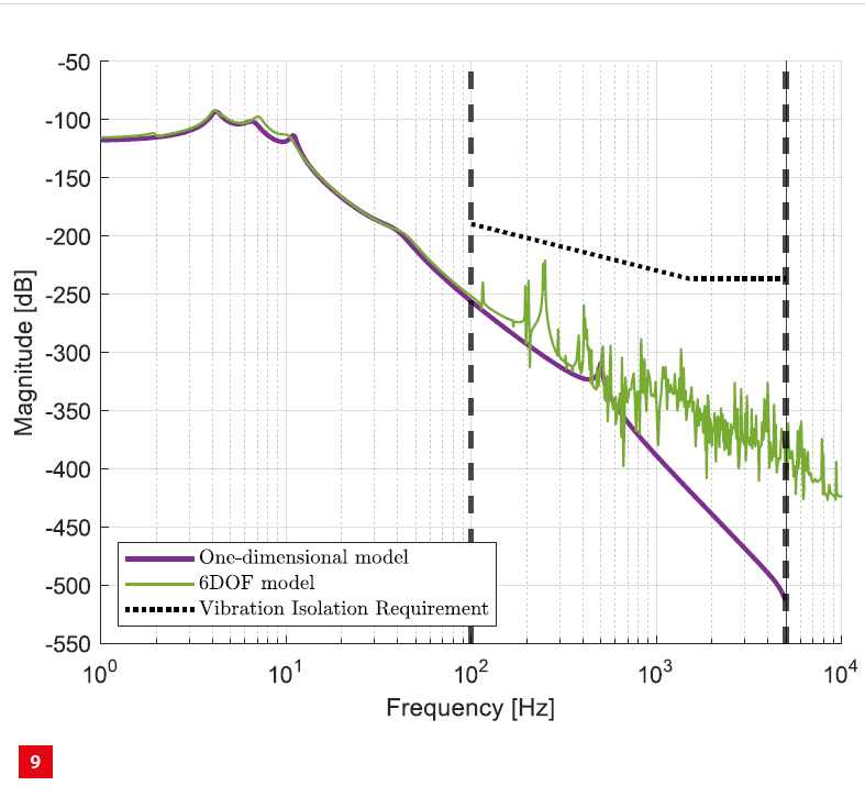
Comparison of the transfer functions derived from the 1-DoF model and the 6-DoF FEM analysis, respectively.
Semiconductors, optical satellite communication, smart industry – these are just some of the domains where we as TNO join forces with the high tech industry in The Netherlands, every day. Together, we innovate and truly make an impact, for a safe, healthy, durable and digital society.